Finite Element Analysis
The Future is Now
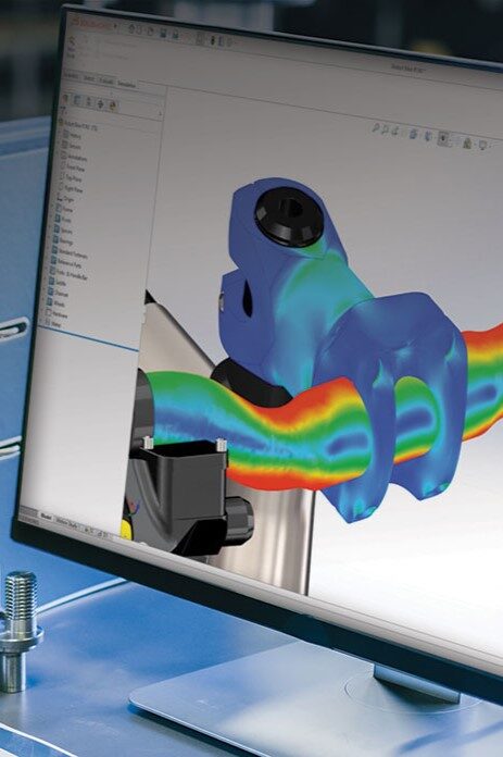
Level 3 Fitness-for-Service assessments may require Finite Element Analysis (FEA) to conduct in-depth studies of pressure, contact forces, vibration loading, thermal loading (heat flux), and fatigue. At CANEIL, we utilize SOLIDWORKS Premium to model and assess pressure vessels, tanks, and other equipment with complex geometries. For piping systems and pipelines, we rely on CAESAR II, a powerful tool that allows us to accurately analyze and evaluate the structural integrity of these systems. Through these advanced modeling techniques, we provide precise and reliable assessments to ensure the continued safety and performance of critical assets.
General Steps we Follow
- The problem is evaluated to specify static and dynamic conditions, and generate engineering assumptions.
- Finite Element Models are simplified to reduce computing time and increase efficiency. Partial models may be used when symmetry is present, ensuring faster and accurate analysis.
- Loads and boundary conditions are specified. Combined loading conditions are accounted for using rules from ASCE 7-10 and NBCC for seismic, dead, and live loads. ASME Sec VIII Div. 2 is referenced for fatigue and cyclic stress requirements.
- Mesh size and element types are defined based on curvature and material thickness. Areas with structural discontinuities and stress concentrations are refined iteratively with successive simulations. Additionally, maximum element aspect ratios are checked to ensure optimal mesh quality.
- Analysis results are accepted on the basis of mesh convergence and grid independence. Through the use of the h-refinement method which involves decreasing element sizes to achieve greater accuracy
- For pressure equipment design submissions in Alberta, AB-520 is referenced to ensure fulfillment of ABSA requirements for application of FEA in Fitness-For-Service assessments.
CANEIL personnel have performed a wide range of Fitness-For-Service projects. The following is a summary of just a few of the projects our team has undertaken:
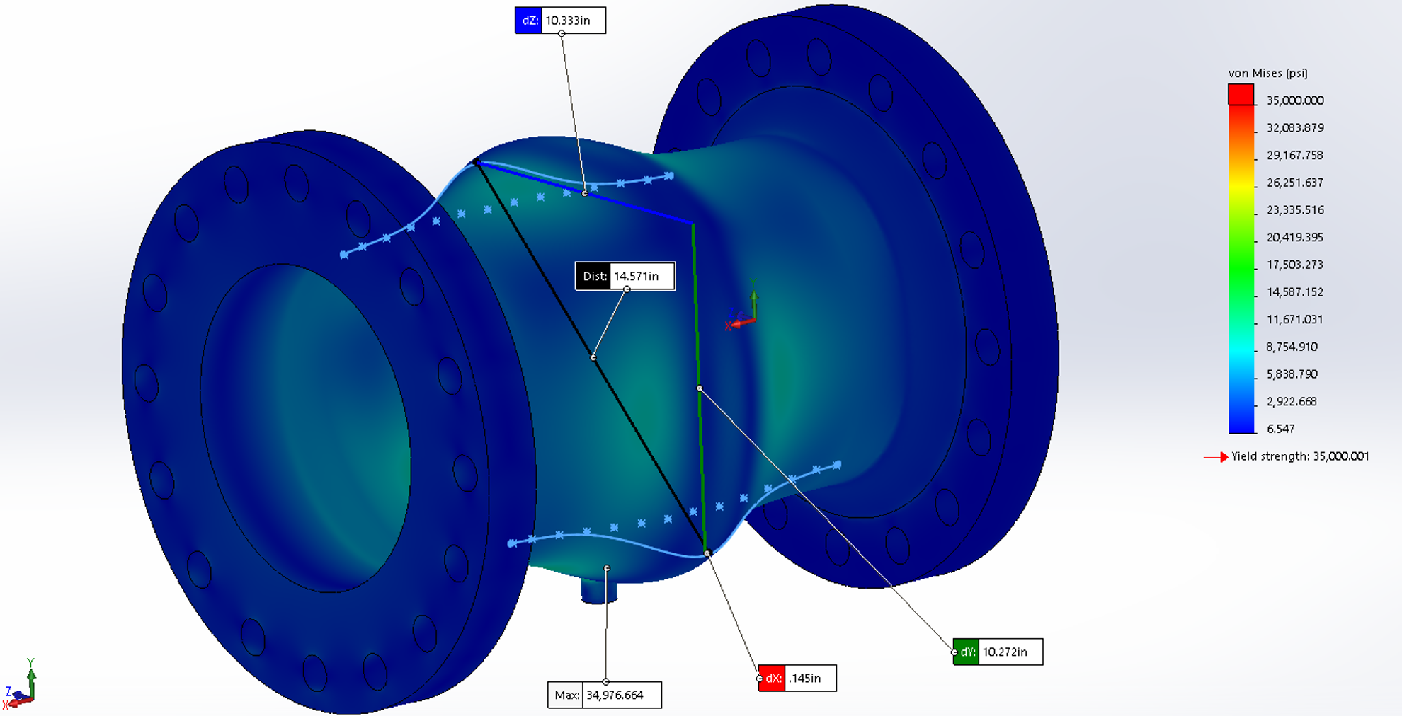
A 10 in. diameter pipe spool in high-pressure steam service was found to be plastically deformed. Due to the nature of the deformation present in the pipe it was determined that a level 3 Fitness-For-Service assessment using the criteria and procedures from API 579 Part 8 “Assessment of Weld Misalignment and Shell Distortions” was the best course of action. A CAESAR II model was created in order to determine the loads on the flanges for the piping spool. The pipe spool was modelled in SolidWorks and a simulation was conducted in order to determine the stresses in the pipe spool. The following analyses were conducted and corresponding criteria were checked as part of the Fitness-For-Service analysis:
- Linear elastic analysis as per Annex 2D of API 579.
- Protection against plastic collapse verified by simulation convergence and applicable criteria from ASME Sec. VIII Div. 2 Part 5.
- Protection against local failure was verified by checking stress limit criterion from ASME Sec. VIII Div. 2 Part 5.
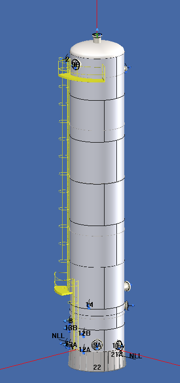
A process tower was identified to have an area of metal loss near the bottom of the vessel exceeding the original design corrosion allowance. A model of the process tower was created in Codeware Compress software, taking into consideration wind and seismic loading conditions. The forces and moments on the tower as well as the required thickness values at each of the shell sections were determined. A fitness for service evaluation using procedures and criteria from API 579 Level 2 Part 4 “General Metal Loss” was conducted to determine if the process tower was safe for continued operation in its current state with the area of metal loss present at the base of the tower.
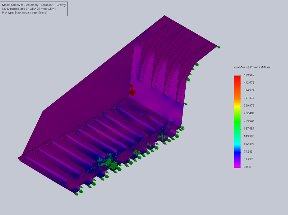
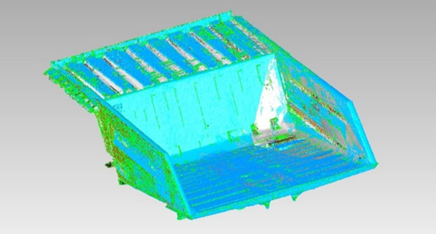
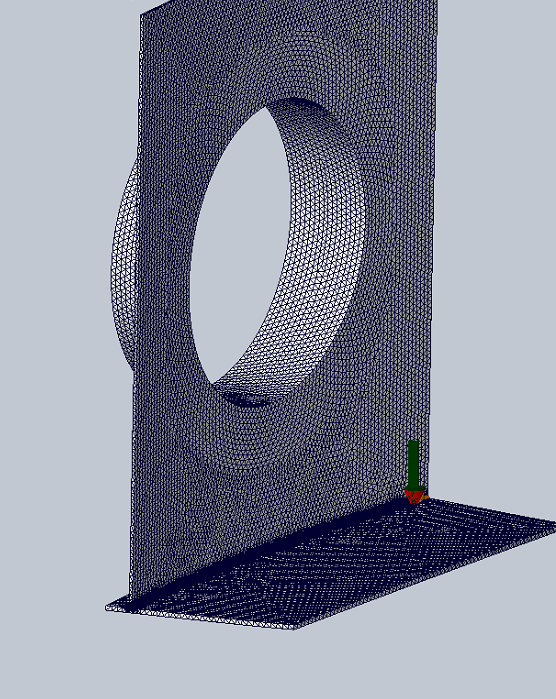
CANEIL was tasked with investigating a high number of recurring cracks and welding repairs on a fleet of haul truck dump bodies. Structural analysis was conducted in SOLIDWORKS to identify the causes of the frequent damage, and propose solutions to reduce cracking and ensure the longevity of weld repairs. A 3-D laser scan of the truck body was performed in the field, and used to support more accurate modelling of the structure in SOLIDWORKS.
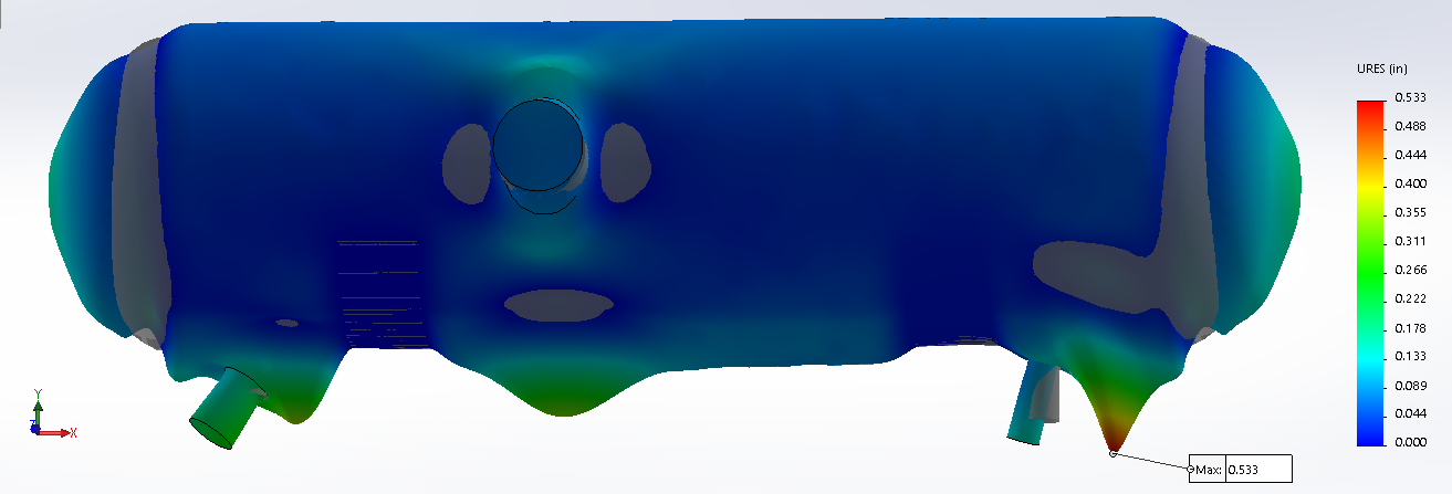
A level 3 API 579 assessment was performed on a de-hexanizer pressure vessel to determine whether plastic collapse would occur. The FEA was performed concurrently with an FFS assessment of weld misalignment and shell distortion using API 579 Part 8. A screenshot of the model in SolidWorks is provided below.
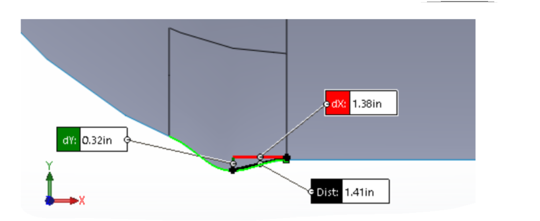
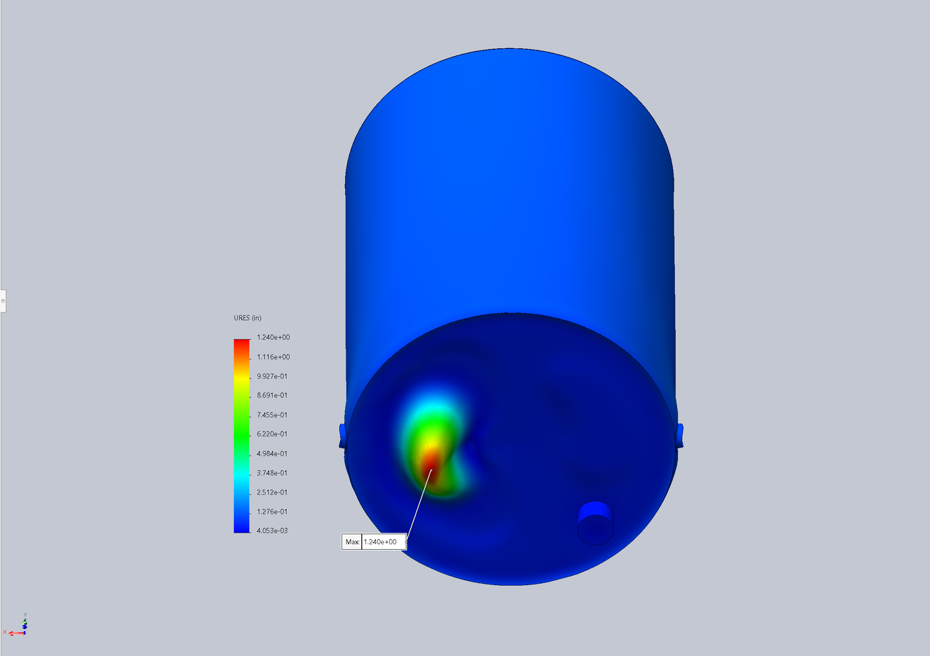
A Finite Element Analysis study was conducted for a tank undergoing uneven floor settlement leading to deformations in the floor and lower tank regions. The tank was modelled with and without deformities in SolidWorks to create a baseline comparison and assess critical stress regions. The maximum liquid level and remaining life of the tank were also calculated.
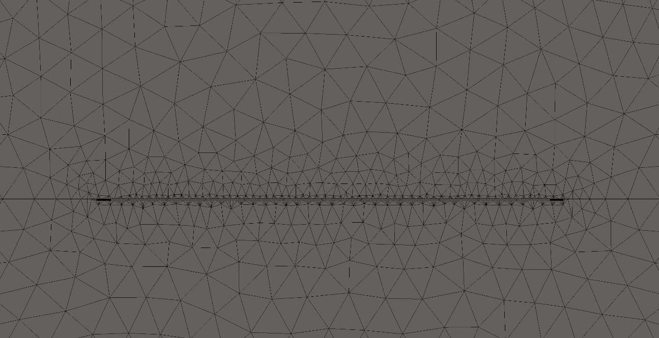
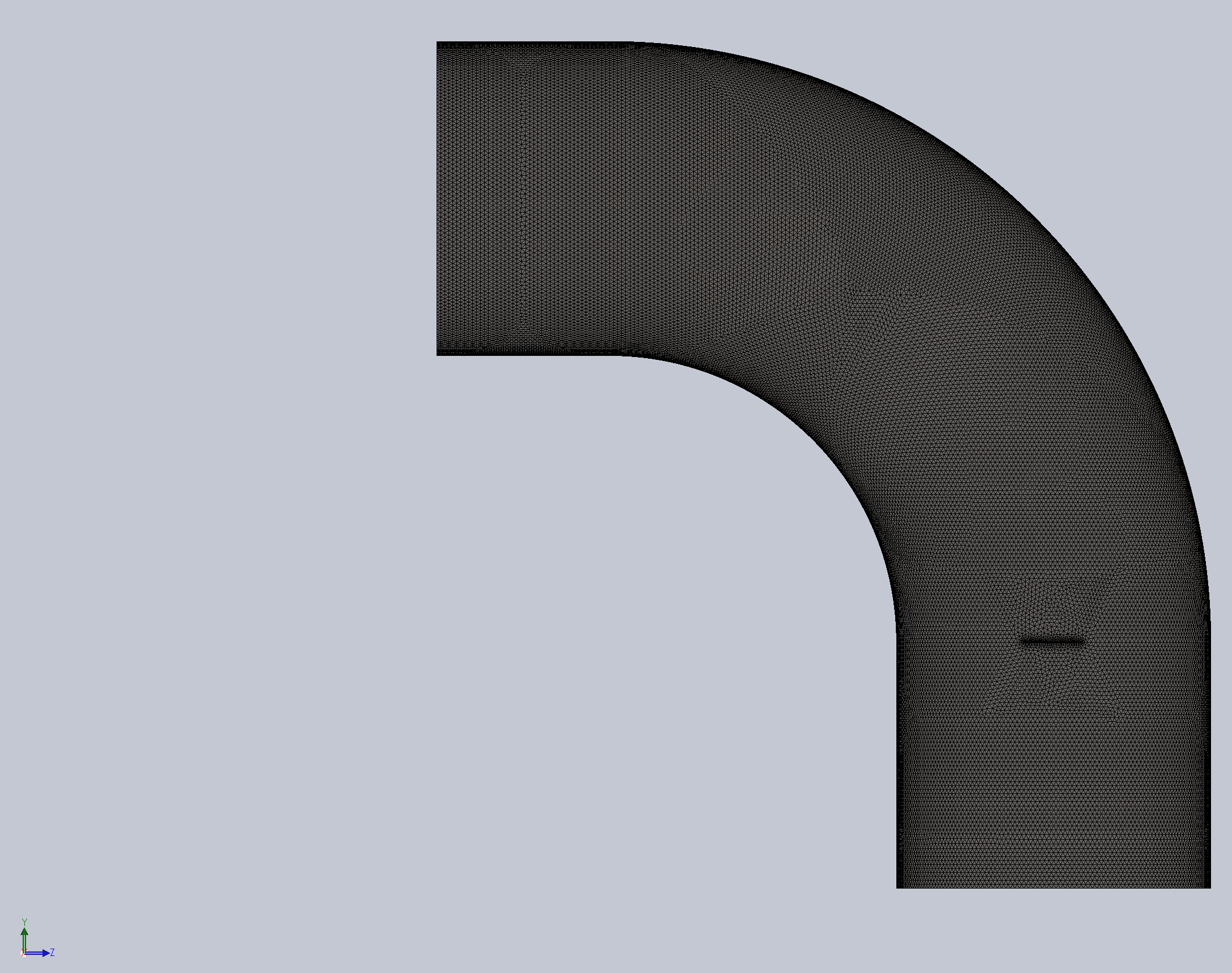
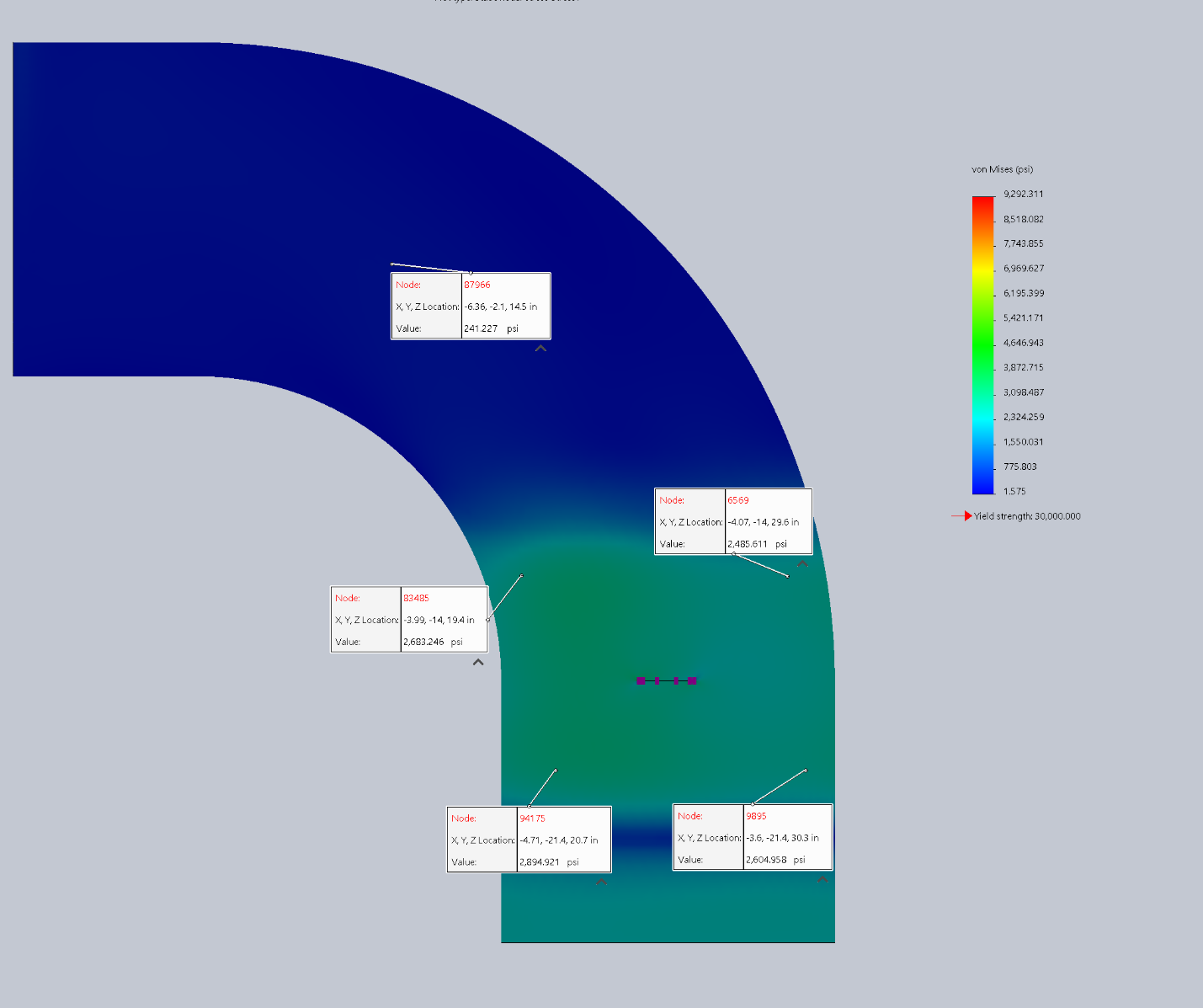
A stress analysis study was performed on a 57 mm crack located on a curved pipe section. Mesh refinement was performed near the crack to ensure stress concentrations are accurately computed and convergence is achieved. Additionally, linearization of the membrane stress was performed across the vessel wall thickness. The principal stresses, Von Mises stress, displacement, and stress values along the pressure vessel wall thickness were assessed and compared with yield stress values of the material.
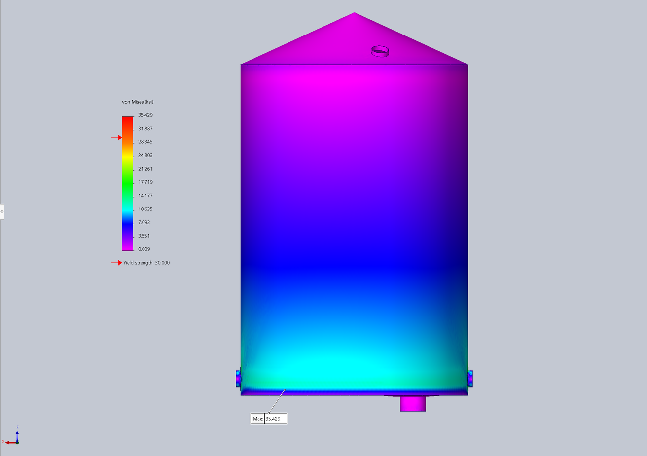
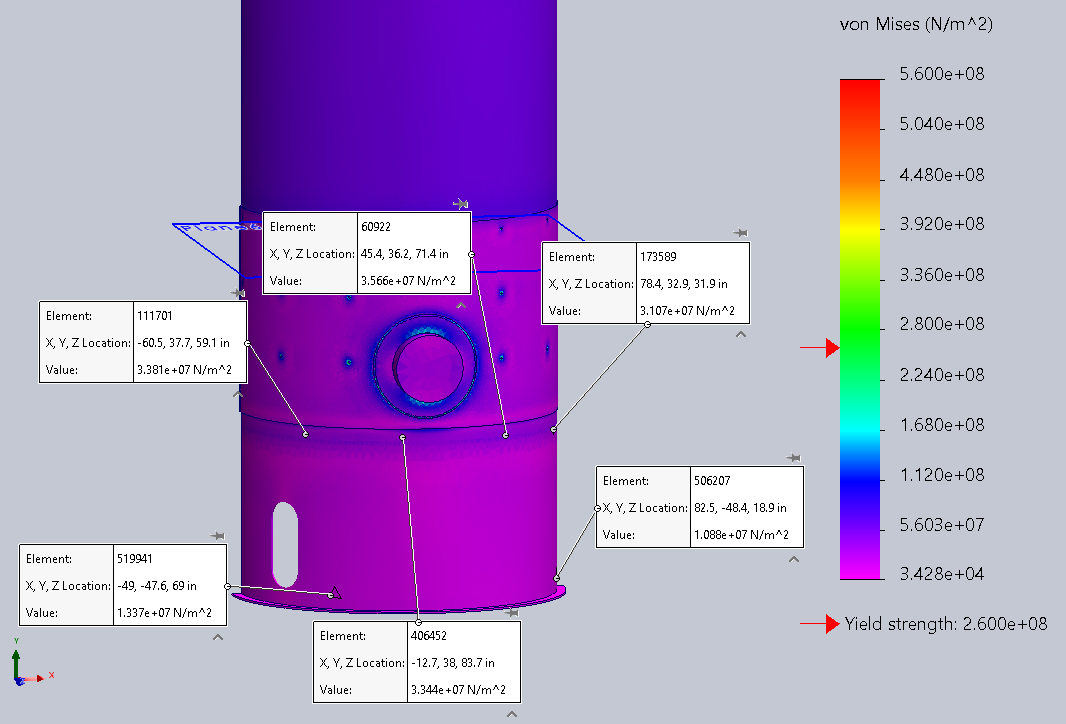
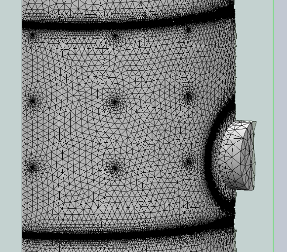
A Fitness-For-Service assessment was performed around a corroded shell course for a Pressure Leach Flash Vessel to determine stress levels at critical locations. The impact of attaching a 0.5-inch cover plate over the original circumferential welds of the shell course with plug welds distributed every 30° was modelled and analyzed.